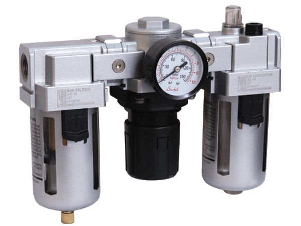
The Things You Need To Know About FRL Unit

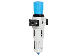
FRL Unit – Pressure and flow curves are typically used by FRL Units manufacturers to calculate the pressure loss and dirt holding capacity. Accordingly, particle-removal filters should be selected based on the acceptable pressure drop and pipe connection size.
Through such filters, the pressure drops typically range between 1 and 5 PSI. As a result, a larger filter will have a longer service life and produce less initial pressure loss.
In most point-of-use filters, condensed water is claimed to be removed by a cyclone separator at the inlet end. Although, the efficiency of such filters in removing water is very dependent on the velocity of the incoming air. Thus, these filters must match the intended airflow rather than the acceptable pressure drop.

To remove accumulated liquids from the filter bowl periodically, a float-type drain should be installed if the filter is intended to remove moisture. This filter’s transparent polycarbonate bowl makes it easy to see the sump level.
Numerous chemicals can attack this material, and it is only effective at temperatures between 40° and 120° F and pressures below 150 PSI. Metal bowls are required for filters subjected to conditions beyond those limits. A metal bowl is also necessary when synthetic compressor lubricants are used, which contain chemicals that damage polycarbonate.
Coalescing Filters
Compressed air streams contain most oil and some condensed water in the form of mists or aerosols, which pass through standard airline filters. Such droplets must be removed from the air for instruments, spray painting, and bulk-material conveyance. This can be accomplished by coalescing-type filters.
Typically, aerosol carryover through such filters is measured in parts per million (ppm) of oil vs. air by weight and ranges from 1 to 0.01 ppm. Aerosols smaller than the nominal size of the smallest solid particle that can be captured are often removed by coalescing filters. On some models, two stages of filtration are available. To protect the coalescing element, the first stage removes solid particulates.
Because coalescing filters restrict airflow more than conventional compressed air filters, pressure losses will be higher. Based on pressure and flow rate, coalescing filters have an initial pressure drop (or dry pressure drop) and a working pressure drop (or saturated pressure drop). As a result, the effective removal efficiency of such filters is strongly influenced by the air velocity passing through the filter assembly.
Coalescing filters should be selected based on acceptable oil carryover, airflow rate, and pipe connection size. In contrast, when a high-efficiency filter is wetted or fully saturated during service, a coalescing filter rated at 0.01 ppm can cause as much as 10 PSI pressure. Once wet or fully saturated, it will drop.
Choosing the Right Pressure Regulators
 Regardless of the upstream flow and pressure fluctuations, it is necessary to supply the air at constant pressure, as soon as the minimum suitable operating pressure has been determined for any compressed air application. Installing the proper regulator or pressure-reducing valve in the airline is therefore crucial.
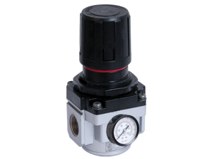
Specifically, air regulators reduce supply pressure to the level necessary for downstream pneumatic equipment to operate efficiently. A filter should always be installed upstream of the regulator in order to prevent damage to its internal passages.
A Poppet Style Valve
An unbalanced-poppet-style valve is the simplest type of air regulator. The design incorporates an adjustment spring, does not have a separate diaphragm chamber, and is not relieving. Turning the adjustment screw compresses the spring, which exposes an orifice with a poppet by moving the diaphragm.
As the downstream pressure increases, it acts on the underside of the diaphragm, counteracting the force of the spring. To produce the desired downstream pressure, the poppet restricts the orifice opening. By placing a spring under the poppet, the valve closes completely when there is no flow. This type of air regulator is the least expensive.
Chambers of the Diaphragm
Larger, more expensive regulators have a separate diaphragm chamber that exposes an aspirator tube to the output pressure. Separating the diaphragm from the primary airflow minimizes its abrasive effects and extends the valve’s life.
The aspirator tube lowers the pressure in the diaphragm chamber as the flow through this regulator increases. As a result, the diaphragm deflects downward and opens the orifice without lowering the output pressure significantly. This is equivalent to increasing the adjustment setting. As a result, this style of the regulator has a minimal drop in output pressure when the supply pressure changes. In the table below, we compare how that variance occurs with a small and a large diaphragm.
These regulators have larger diaphragms, which improve response and sensitivity. Over the regulator’s entire range, output pressure decreases as discharge flow increases. Therefore, it is imperative to set the regulator’s desired output pressure under typical flow conditions.
Precision Regulators and Balanced Poppets
Other types of regulators are constructed similarly to the separate diaphragm versions, but they have a balanced poppet. It has a significantly larger orifice for better airflow. The poppet is pressure-balanced for stability. This reduces droop and enhances sensitivity, as well as the cancellation of fluctuations in output pressure.
Last but not least, precision regulators are often constructed with several isolated diaphragms working as a balancing principle against flapper valves and nozzles and are normally designed with smaller connection ports and limited flow capacities.
Regulators to Consider When Selecting
Choosing among these styles is the first step in choosing the best regulator for a specific application. A mini-regulator is a direct-acting, non-relieving device, while a standard regulator features a separate diaphragm chamber and self-relief.
Primary (unregulated supply) pressure versus desired secondary (output) pressure is the next consideration.
Finally, the desired airflow rate must be chosen. Two types of adjustment screws are available: a tamper-resistant, locking Tee type or a push-lock, plastic knob type. In the first case, the operating pressure should be set once and left alone. Nevertheless, the adjustable knob style (quite common on modular FRLs) is a better choice for general use, since operating pressure can be altered without tools. Regulators can also be classified by their body size (orifice flow rating) and connection size.
A large body size regulator will produce better setting sensitivity and less droop under the same set of operating conditions as a smaller body model, regardless of airflow and pressure.
It is essential to have a gauge to measure output pressure, although many manufacturers only offer it as an option. A mounting bracket is another useful accessory.


